Principle of Trimmer Potentiomerets
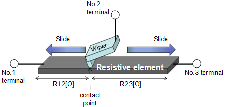
A fixed resistor with a mechanism to change resistance construct a trimmer potentiometers. The principle is with the changing of resistive element length according a wiper sliding, the resistance will be changed. Use this method, with same sectional area, the resistance can be changed relative to resistive element length, and products can be manufactured in low cost.

R: Resistance [Ω]
ρ: Resistivity [Ω/m]
L: Resistive element length [m]
S: Resistive element sectional area [m2]
- The position of contact point decide the length of resistive element.
Resistance between No.1 and No.2 (R12) will become higher if contact point become closer to No.3. - For easy introduction, we drew the resistive element like a rectangular solid. Actually, almost resistive element is round shape
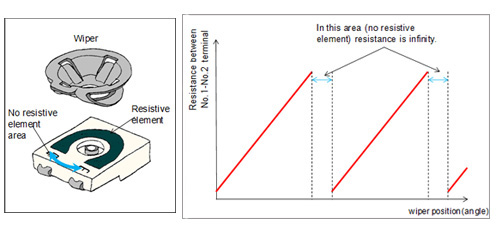
(U - shaped) .So the track of wiper is circle, and resistance is decide by the angle of wiper.
Change in resistance of Trimmer Potentiometers
There is the relationship between wiper position (angle) and resistance in below figure.
The output wave is besed on below conditions.
Resistive element is round shape (U - shaped) /Single - turn/No whirl - stop.
Construction
Single - turn, no whirl - stop typ The relationship between wiper position (angle) and resistance
Feature of Trimmer Potentiometers
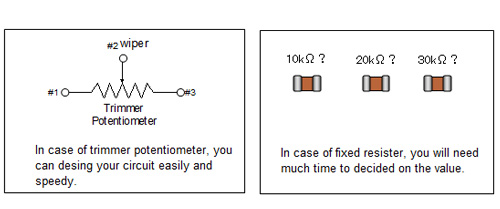
By using trimmer potentiometers, it is no problem to set surrounding circuit constant roughly.
Would you please use trimmer potentiometers if it is difficult to decided on a resistance value in your circuit. You can design your circuit roughly and quickly as the result.
